

LED Video Screens For Physical Computing
With Teensy & MadMapper
Welcome! This page contains (hopefully) all the material covered in my ITP Camp Session on June 17th 2020 along with additional resources and video tutorials to be referenced during the session.
For those of you who missed the session or got here through the web, this page covers how to set up large scale LED installations from scratch with WS2812b (or other types) of LED strips, how to manually code them with a Teensy (allowing for integration with physical sensors and actuators in the same way as an Arduino), as well as how to map and play video or texture / shader content on the LEDs through MadMapper.
To the right you can see a live LED mirror using webcam input.
Below you can see some video animation mapping examples.
One thing to note is that these look much different and better in person, it is very hard to capture LED lights on camera, especially from home with an IPhone.
Schedule / Topics Covered:
Bill Of Materials : Everything you need to build a large scale LED video display
LED Strip Basics: How LED strips work, power calculations
Teensy + Octo Shield: How we are going to communicate with the LED strips
Building The Circuit: Soldiering strips together + connecting the computer -> teensy -> octo shield -> led strip via Ethernet'
Directly coding LED strips through Arduino IDE (Teensy is an Arduino compatible chip)
Mapping With MadMapper
Bill Of Materials:
LED Strips - pretty much any addressable 5V RGB strips should work with a Teensy. For this tutorial, I will be using ALITOVE 16.4FT 300 Pixels WS2812B Programmable Addressable LED Strip Light Black PCB 5050 RGB Dream Color Flexible LED Rope Light DC5V Not Waterproof ~ $30
Teensy 3.2 (with pins if you don’t want extra soldering) ~ $25 (you will also need a micro usb to connect the Teensy to the computer if you don’t have one)
Power supply - depends on how many LEDs you want to control. We will cover how to calculate power requirements but for 300 LEDS running at 100%, you need a 5V and 18 or more Amp power supply. Both of these can power 1000 leds at max brightness this one is cheaper , this one is quieter and smaller ~$25-35
AC Power Cord - any extra laying around will work, we will be destroying it to connect the power supply to the wall outlet. ~$6
Wire for connecting LEDS - this is up to you, pretty much any regular connector wire will do - I usually use stranded core 22 AWG wire because it provides 4 different color strands and can bend without breaking ~$5-20
Power distribution Terminal Blocks - we need to have multiple lines powering the strips, these allow us to distribute power and ground signals to strips periodically ~ $12
Wire to connect power supply to terminal block - we can’t use thin 22 AWG wire for this because there is so much current it will melt the wires. I use 14 gauge speaker connector wire ~$8
An Ethernet cord - any laying around your apartment will do but we will be destroying it ~$6
JST Connectors (optional) - wires with connecting plugs that allow you to take your circuit apart for storage or transport.
A MadMapper license - MadMapper has been kind enough to grant me student licenses for this class! If you don’t want to use MadMapper, there is plenty of programming possible with just the Teensy.
Soldiering Iron, Soldier, Wire Cutter, Helping Hands etc.
LED Strip Basics
Before we start getting in to the details of LEDs let’s do a short review of some fundamentals of electricity.
Voltage: potential electrical difference between two points - makes electric charges move. It is the 'push' that causes charges to move in a wire or other electrical conductor. You can imagine voltage is similar to the water pressure supplied to a hose. Voltage is measured in Volts (V)
Current: the flow of electrical charge through a material. You can imagine current is how much water is flowing through the hose. Current is measured in Amperes and is usually denoted by the letter I.
Resistance: measures how the device or material reduces the electric current flow through it. You can imagine resistance is correlated with how narrow or long the hose is which determines the current. Resistance is measured in Ohms (R or Ω)
Voltage, Current, and Resistance are all directly related by a formula called Ohms Law which states that Voltage = Current x Resistance or V = IR. To go back to the hose analogy, we can imagine a house has a set water pressure (V) and we can calculate the speed at which water is traveling through the hose (I) based on how narrow the hose is and how long the length is (R).
Watt: The standard unit for power or the rate at which electrical energy is dissipated. LED strips have a specific amount of power drawn per LED, found on the data sheet. Watts are equal to Voltage x Current.
Ok, just keep that info in the back of your mind, or refer back here when necessary. We will use it to determine how much power is necessary to drive the LEDs soon.
Types Of LED Strips
LED strips can be broken into two categories, addressable and non addressable. Non addressable strips are what you often see in architectural applications, the lights in an elevator, IKEA lamps, etc. These LEDs are all controlled at the same time (all are on or off, and they all have the same brightness). These strips only require a Power line (Voltage) and ground line. Addressable strips are what we will be working with today. These strips have data lines that go to every LED, this gives us individual control over both the brightness and (color or color temperature of each LED). If you want more information about addressable LEDS, check out Tom Igoe’s blog.

WS2812B Strips
These are the strips we will be working with today and as far as I can tell the most common strips used by hobbyists. I have heard evidence that APA102s are better / brighter, I can’t really tell a difference when I have used them although I am usually not too concerned with the refresh rate / occasional data loss because the LEDs are usually diffused or stretched quite a bit.
On the right you can see a WS2812B strip up close, it includes the IC driver connected to a 5050RGB LED.
One thing to note is that there are many many types of LED strips, some have direct control over R, G, B, some strips have a fourth white led, others have a white, amber, and cool white led.
If you are interested, here is a chart of the most common LEDs on the market.
Power Calculations
How do we know how much power we are going to need to drive our LEDS? We look at the data sheet and use our electrical fundamental knowledge from above. Here is the amazon description from the strips:
Light source: 5050 RGB LED with built-in WS2812B driver IC
LED Qty: 60 LED/M, 300 LED/Roll
Wave length: R,620~625nm ; G,515~525nm; B,465~475nm ; 24 bit full color ; 256 gray levels ;
Working voltage & power: DC 5V; 0.3W/LED; 18W/M; 90W/Roll
Dimension: (L)5000mm * (W)12mm * (H)4mm; 16.4ft/5m per roll
Port scanning frequency reaches to 2KHz/s ; Data transmitting speed is up to 800Kbps
RGB order: GRB (Not RGB) ( Please set up the controller before you use it. )
Wire instruction: Red wire: 5V+ ; Black Wire: GDN ; Green wire: Data
Life span:≥50000hrs; FPCB color: Black
Ok, so we know from the line in bold that each LED takes up .3W (watts). Watts if we look above = Volts * Current. We know we are working with 5V LED strips, so we just have one variable to solve for: Current (I).
.3 Watts = 5 Volts x ? Amps …… Amps = .3/5 = .06 Amps Per LED
How many LEDs do we want to use in our installation? Let’s say two rolls of Neopixels so 600 LEDs * .06 Amps Per LED = 36 Amps
We now know that we need a power supply that provides 5 Volts of power and at least 36 Amps (it is not an issue to have more amps, it is an issue to have too many volts).
Teensy + Octo Shield
What is this Teensy thing? ….. It is just an Arduino.
Why do we need it? ….. It is fast!
Can we just use an arduino? ….. Yes but an arduino nano has a 16 MHz processor, a Teensy 3.2 has a 96 Mhz processor (6 times faster which is necessary for running big LED displays without glitching.
The teensy + octo combo is great because it provides access to 14 pins on the teensy which can be used for your standard arduino functionality (digital and analog input and output / PWM etc). It also has a +5V and GND pins so that you can power your teensy without the micro usb for standalone installations.


What is the Octo Shield?
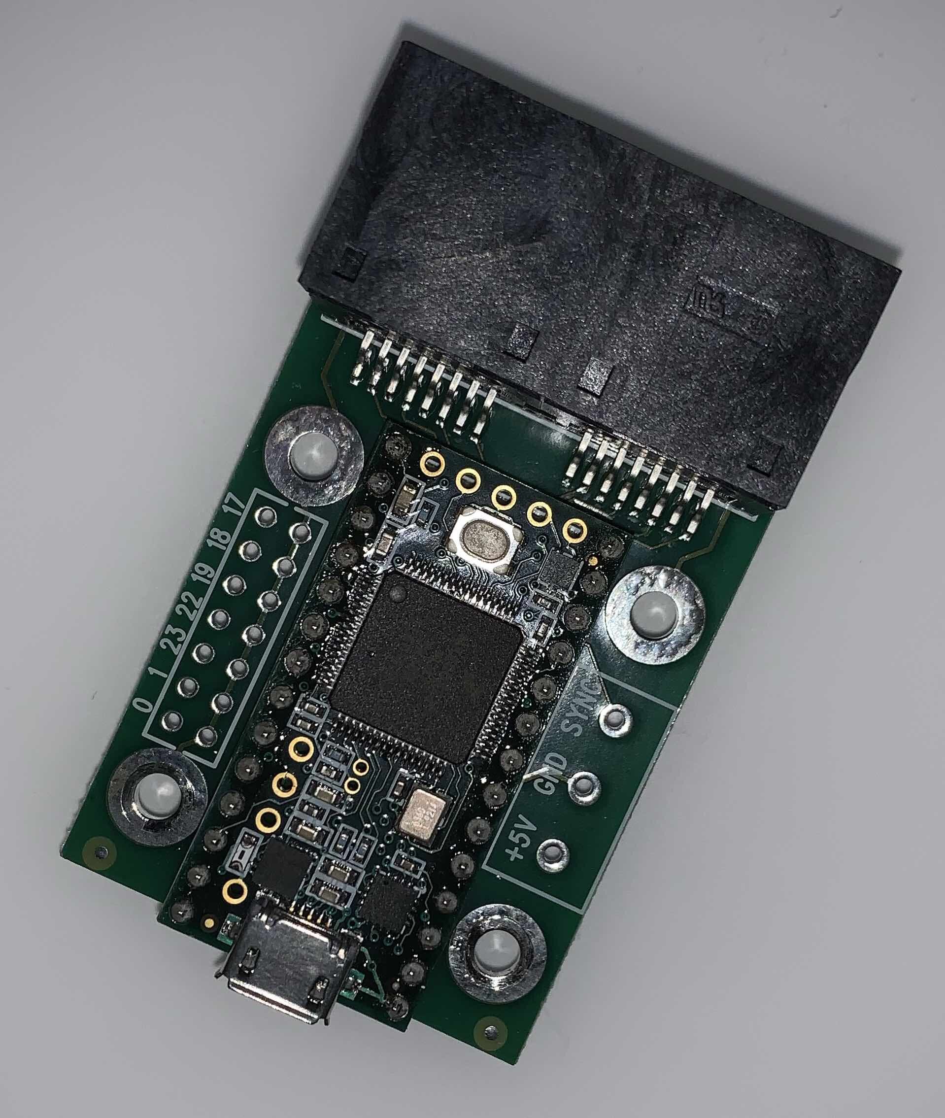
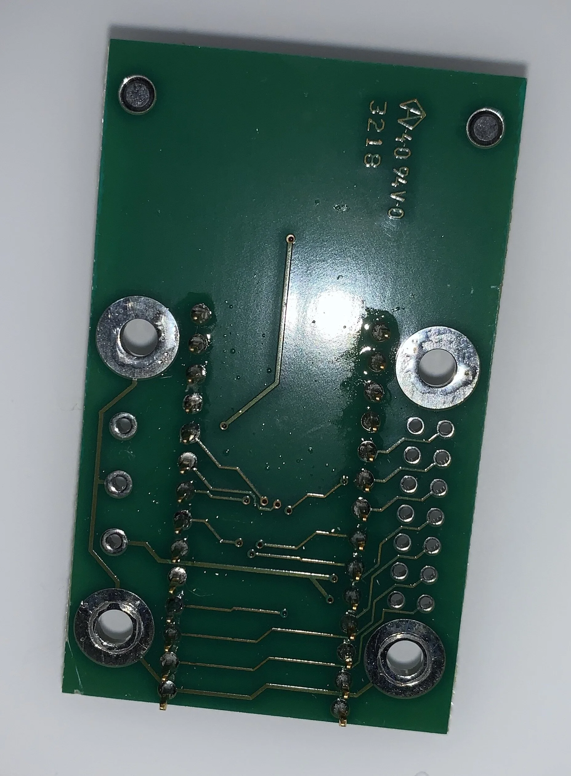
The octo shield is a chip that the teensy is soldiered into that provides a buffer, a signal amplifier (3.3 v teensy signal to 5v led data signal) and an ethernet adapter (Cat6). This provides for a much more reliable signal out of the teensy.
You will need to soldier the teensy onto the octo shield. Unfortunately, while I have multiple teensies and octos laying around, they are all already soldiered together. The teensy should hopefully have come with pins soldiered to it already. You just have to pop it onto the octo shield, tape it or hold it with helping hands and soldier all the pins on the bottom.
Here is a link to someone soldering the teensy pins (you will have to follow the same technique only to the flip side of the octo shield after placing the teensy on top. Below is a picture of the end result.
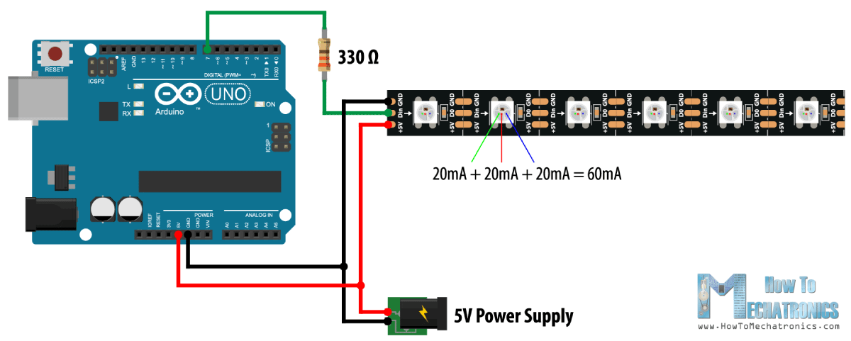
But wait, I don’t want to buy a teensy, I just want to control some strips with an arduino I already have…..
For those that are not interested in big LED setups and want to control the LEDs manually with code, here is a circuit using an arduino Nano to control the strips (note the resistor that is necessary for an arduino but not necessary if you use a teensy).
Building The Circuit
Ok, this might look a bit overwhelming but I will cover everything step by step.

The power supply
When powering lots of LEDs, we are going to require a lot of current. We know that for 600 LEDS, we will need 36 Amps (see calculations above). We need to first set up the AC to DC power supply. LED strips usually take +5 v or +12v DC current, the power that comes out of the wall is 115 V AC (USA). We need to convert the AC to DC with a power converter.
Grab your AC power cord and cut off the female end. Then use wire strippers to score the sheath so that it can be ripped off exposing the three wires inside. Then strip each individual wire, leaving about half an inch exposed. We are then going to wrap these wires around the screws in the power converter and plug them into their respective terminals. The Black wire is Load (L), the White wire is Neutral (N), and the Green wire is Ground (horizontal lines). We also want to connect the Ground Terminal (horizontal lines) to V-. This connects the ground of the AC circuit with the ground of the DC circuit which is best practice and safer (although I have never seen anyone have trouble if they don’t do this).
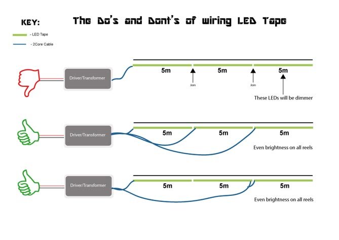
Next we are going to connect our power supply to the terminal block. This is used because we need to feed / inject power to each group of about 60 LEDs. This is due to voltage drop in the wires and led driver chips. Basically we loose voltage as we light up the LEDs which will cause them to become dimmer the more we have. If we feed power and ground to each group of 60 or so LEDS, all of them will stay bright. Please see video for more details on how to set all of this up. Make sure to use low gauge (14 AWG) for the DC output, if you use skinnier wires they are going to get hot and potentially melt.

Strip outside tube, strip each wire, twist wires into half loop.

Connect V- and GND, green wire to GND, white wire to N, black wire to L

+5V DC and GND to terminal block, connect 6 GND, 6 5V
Options for power injection. You need to send ground and data lines to each group of ~60 LEDs.
Teensy + Octo To LEDs
For now we are going to ignore the software side of the Teensy + Octo and go ahead and wire them up. We want some LEDs connected so that we can test that our code and circuit is setup properly.
We are going to be sending data to the LEDs via an ethernet cord. There are two plugs on the octo shield which can handle up to 8 separate data lines coming out of the Teensy (each ethernet has 8 wires, 4 pairs of data/GND wires). MadMapper’s teensy code only handles two lines of data. For this project, we are only going to worry about one data line. For reference, I have controlled over 1000 LEDs on one data line without any issues.
First we have to cut open the ethernet cord. I recommend to fold it in half and cut it at the middle. This allows you to have another cord ready to go for a future project (or if you want to get fancy and have multiple data lines from each ethernet socket out of the teensy). After cutting the cord, you are going to want to take scissors or small wire cutters and cut the outer tube exposing the four sets of wrapped wires inside. The colors of the wires correspond to specific output pins of the Teensy. We are going to want and couple inches of wire to work with so cut the outside tube, pull it apart carefully as to not break the tiny wires inside, then cut off all of them besides the wrapped orange and white wires (you could use any color but you need to know which one you are using so you can set the corresponding pin number in the code, in this example we are going to use the orange line). Next strip the small orange and white wires, carefully, making sure that the strands inside are intact. We are going to be soldering these two wires to a JST connector (this is not necessary, you can soldier straight to the LEDs but it is worthwhile because it makes it more modular, easier to take apart, and less likely to break unexpectedly). After soldering the Orange ethernet wire to the JST data line green or whatever color your JST happens to be, and the white ground from the ethernet to the JST ground line (white in my case maybe black in yours). We don’t care about the red wire because LED power is not coming from the ethernet cord. We then use some electrical tape to cover the soldier joints, then connect the red and black wires coming from the LEDs to the terminal block. We want to use a small number of LEDs to test. Because of voltage drop, explained earlier, you can’t plug the entire strip in and expect them all to turn on.

Cut ethernet in half down middle, remove outer sheath with scissors and fingers, cut off all the wires but for the orange and corresponding white, strip the tips of those wires, wrap around ends of JST connector (other end will be connected to LEDs data, LEDs ground & power supply ground). We don’t care about the red wire, you can cut it off if you want.

Teensy -> Ethernet (orange and white) to JST (green and white, red doesn’t matter) -> LED strip JST. Power and ground from LED strip to terminal block. The ground from the teensy is connected to the ground from the led strip. If there is no JST on the strip, you will have to connect the ground from the ethernet to the terminal block.
Coding the Strips with TeensyDuino
Now that we have the circuit set up and 10 LEDs connected, we are ready to learn how to program them manually. The first step is going to be installing the Teensyduino software. Instructions can be found here. After the software is installed, we are going to want to run an example program. Open up the basicTest program. If you are using the WS2812b strips found in the bill of materials, all you have to do is change line 43, ledsPerStrip to the number of LEDs you have (at this point should be 10). The “const int config = WS2811_GRB” line is telling the program which strip you have. WS2812 and WS2811 use the same code so there is no need to change. When you run this code, the LEDs should illuminate and start changing colors. You can also use the NeoPixel or FastLED libraries with the Teensy + Octo. I would recommend installing the FastLED library if you want to manually program the strips. Open the blink example, change the number of LEDs to the number you have. Now, unlike in the octo library, you have to set which pin the data is coming from, if you read the Teensy + Octo documentation here and here you will see that the orange wire corresponds to the first led strip which is set to pin 2 on the teensy. Change line 10 to “#define DATA_PIN 2”. Then delete line 11 (WS2812 strips do not have a clock). Next we need to select the strip we are initializing (comment out the neopixel strip on line 18 and uncomment out the WS2812b strip on line 31). We also need to switch RGB to GRB based on the strip documentation found on amazon. If you don’t switch this, the example will blink green instead of red.

Where to find octows2811 basic test
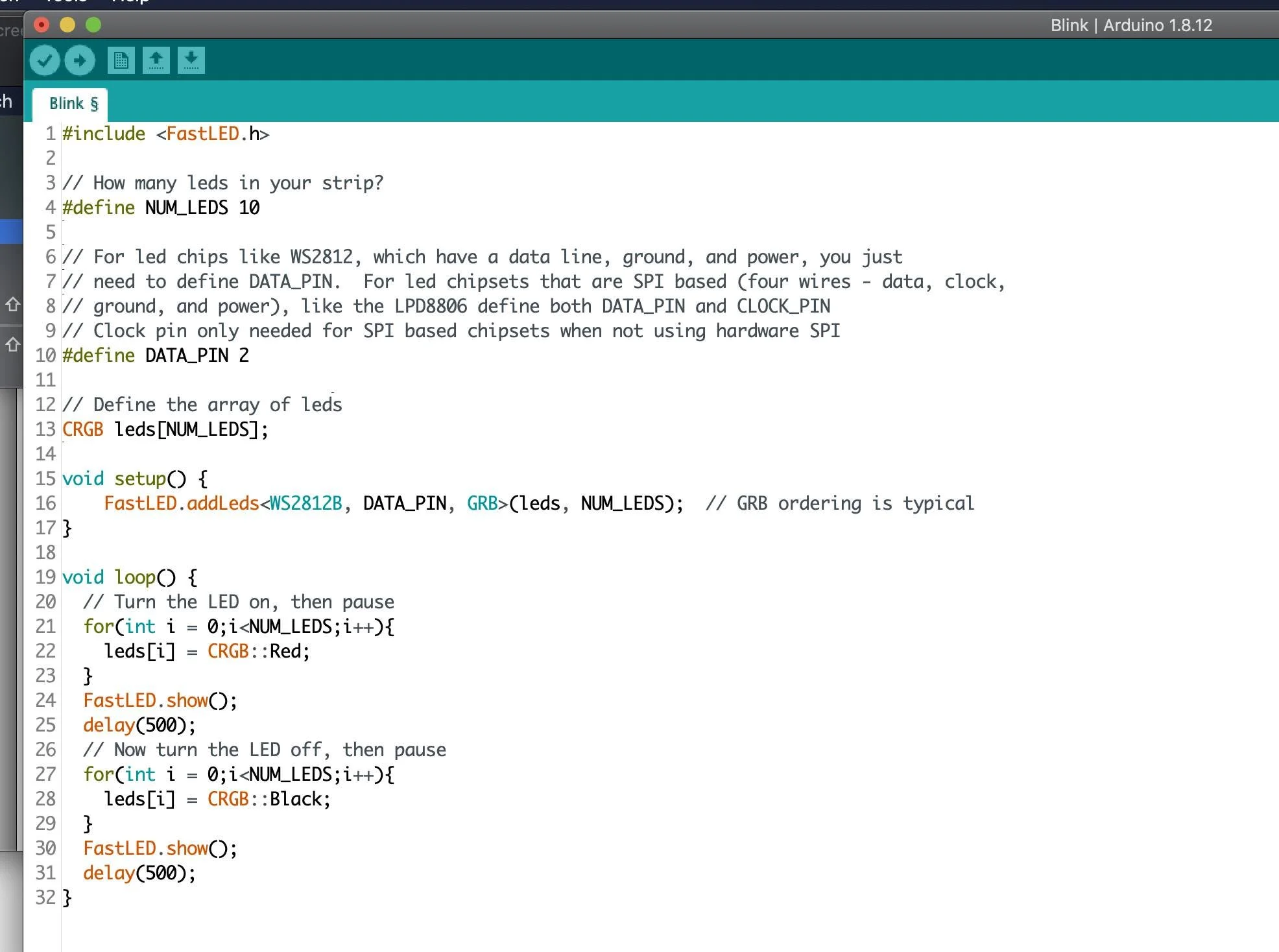
implementation of FastLed Blink that turns 10 leds on and off on WS2812b GRB strip
A little more soldering
Now that we have tested that the teensy + octo are connected to the LEDs correctly, it is time to wire up all the LEDs that we want to use in our installation. For demo purposes, I am going to wire up two more strips of 10 LEDs for a total of three strips of 10 LEDs. In the following video I will demonstrate how to soldier the strips together in addition to explaining power injection a bit more (for the sake of the demo, lets pretend we have significant voltage drop after 20 LEDs so we have to inject power into the third strip. When I am wiring up big LED displays, I like to set the code such that it is trying to turn on the maximum number of LEDs I will be using, after soldering each strip, I turn on the power to make sure that strip is lighting up.
(DON’T SOLDIER STIRPS WITH THE TEENSY ON AND POWER CONNECTED SO YOU DON’T ACCIDENTALLY BURN OUT THE LEDs).
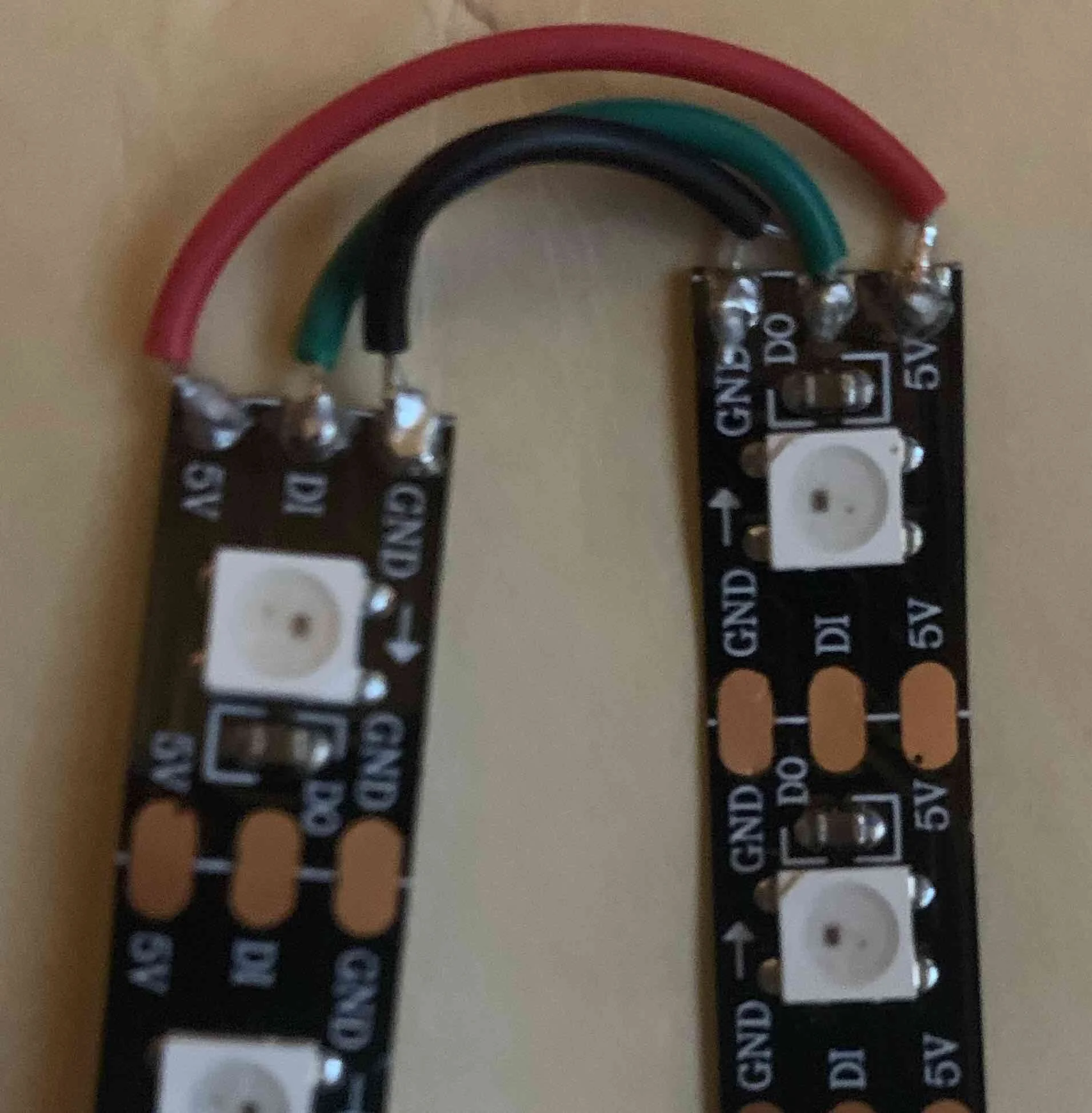
Strip 1-2 (every strip that does not need power injection) match 5V Data and GND to next strip following directions of arrows.

Every 60ish LEDs you will have to add a fresh ground and power line from the terminal block because of voltage drop causing the LEDs to dim and glitch.
Mapping LEDS in Madmapper (BASIC)
Now the fun begins. Before we open MadMapper, we are going to want to upload code onto the Teensy that lets MadMapper send data through it and the Octo to the LEDs. This code is available on their website but I found a bug in it last semester that they fixed but it doesn’t appear that the code has been updated on their site. I would recommend downloading from my github here. The only changes you have to make to it are the number of LEDs you are using, and the strip type if you have anything but WS2812b strips. After you upload onto the teensy, you can open up MadMapper. Below is a video detailing the basic setup necessary to illuminate the 30 LEDs in the tutorial. There is a much more detailed video below for large setups.
MAPPING LEDS (ADVANCED)
Now we are going to move on to a large scale LED example. Displayed below is a large LED display I built in my first semester to display climate change data (why the length is so much bigger than the width). The teensy was connected to a motion sensor which triggered a hard coded animation that I wrote.

Insides of enclosure.

Big LED Screen (520 LEDs)

Live webcam mapping
Mapping Preferences
In MadMapper preferences, navigate to DMX output tab, select ArtNet, ethernet (ignored and sent via usb when you click route ArtNet to usb led devices).

To the right is the routing table. The LED screen we are working with has 40 vertical strips of 13 LEDs each which each have three channels one for red one for blue one for green. This makes a total of 40x13x3 = 1560 channels. In the ArtNet protocol, each universe of LEDs can have up to 512 channels. 1560/512 = 3.04. This means we will need 4 universes of ArtNet.
To make things easy for ourselves, since we have identical vertical strips, we can imagine our screen broken up into 4 identical parts each of 10 strips of 13 LEDS. This means we will use 390 channels per universe / group of 10 strips. We want to start on channel 1 and go to channel 390. On the right side of the table we have an out line and out channel.
The out line corresponds to either 0 or 1 (for the MadMapper teensy integration code). In our case we are just using one line of data. The out channel corresponds to the LED start channel where MadMapper sends each universe of data. The first LED is channel 0, when we get to the second universe, we need to tell it to send that to the 21st strip of LEDS (20x13x3 = 390 = start channel of the second universe (universe 1 due to 0 offset). We add the channel count from the previous universe to the out channel of the previous universe for each subsequent universe.
Fixture Definition
After setting up the routing you want to create a fixture (navigate to DMX tab, click DMX+). Here I have created a fixture that we are going to use 4 times. The fixture contains 10 strips of 13 LEDs each, they are RGB leds, and each pixel has 3 channels. We have to designate our layout based on the way we wired the leds up. I went from top left to bottom, then over and back to the top of the next row. In subsequent projects I learned that it is much easier to snake around saving yourself lots of extra wire that the data passes through that can make the leds slightly glitchy.
After setting up the routing you want to create a fixture (navigate to DMX tab, click DMX+). Here I have created a fixture that we are going to use 4 times. The fixture contains 10 strips of 13 LEDs each, they are RGB leds, and each pixel has 3 channels. We have to designate our layout based on the way we wired the leds up. I went from top left to bottom, then over and back to the top of the next row. In subsequent projects I learned that it is much easier to snake around saving yourself lots of extra wire that the data passes through that can make the leds slightly glitchy.

Mapping Final View
If you have made it this far, congratulations, I am not going to explain everything in the photo on the right, if you are interested, it is all explained in fine detail in the video below.
We can see we have 4 fixtures, they are all the same fixture but each has a different universe associated with it. The fixtures are resized to correspond to their dimensions in real life and arranged side by side. Behind the LEDs, a gif is playing sending the rainbow colors to each led in the red grid. To the right of each fixture you can see which universe and channels of LEDs inside that universe are being sent by ArtNet, you can refer to the routing table above to see which LED channels those values correspond with.
After arranging the fixtures, you can stretch and skew, rotate, add shaders or gifs or videos or webcam input to MadMapper and send directly to the LEDs. You can also set up scenes, playlists, send data via OSC, MIDI, Syphon and much more.
